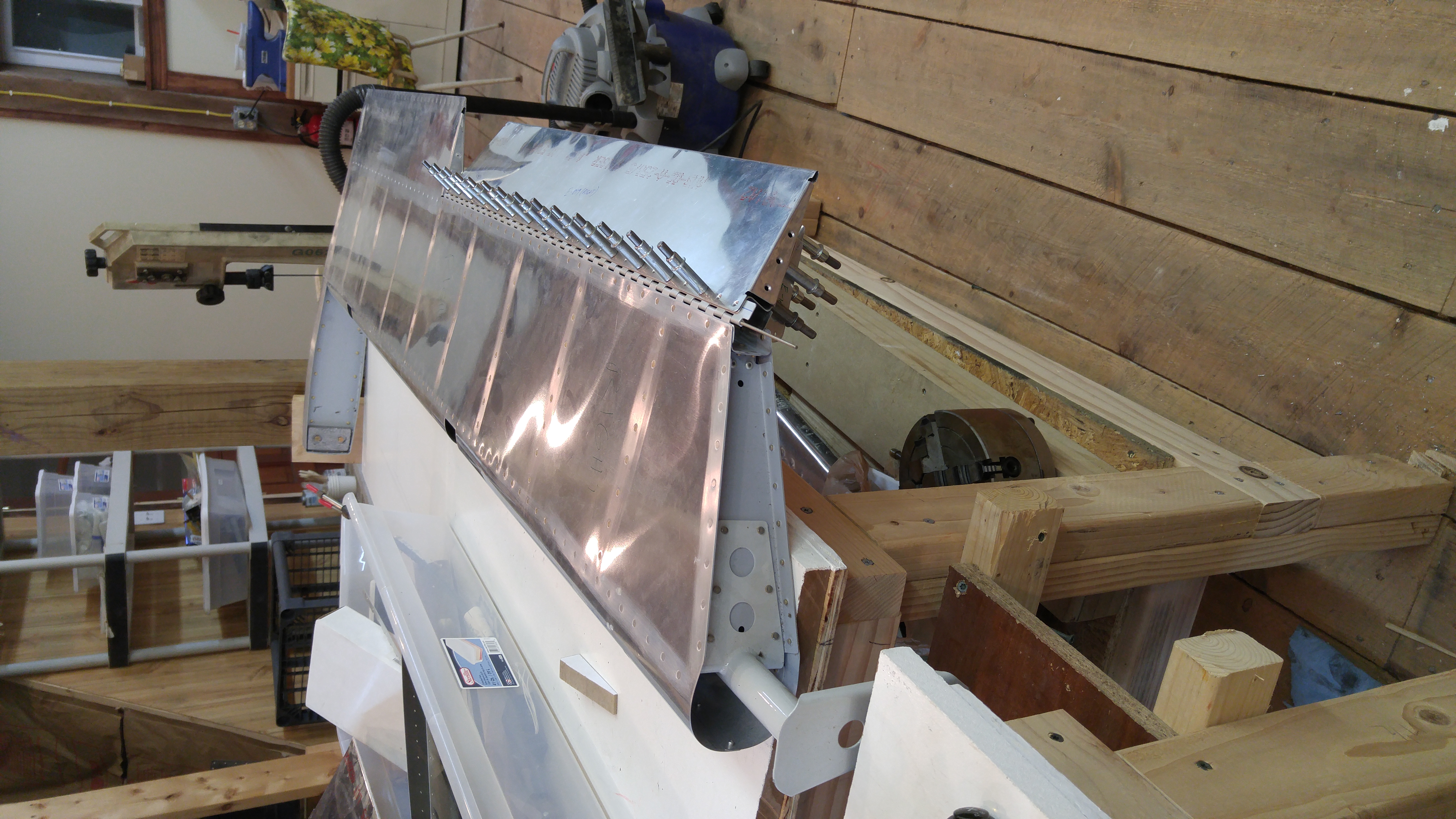
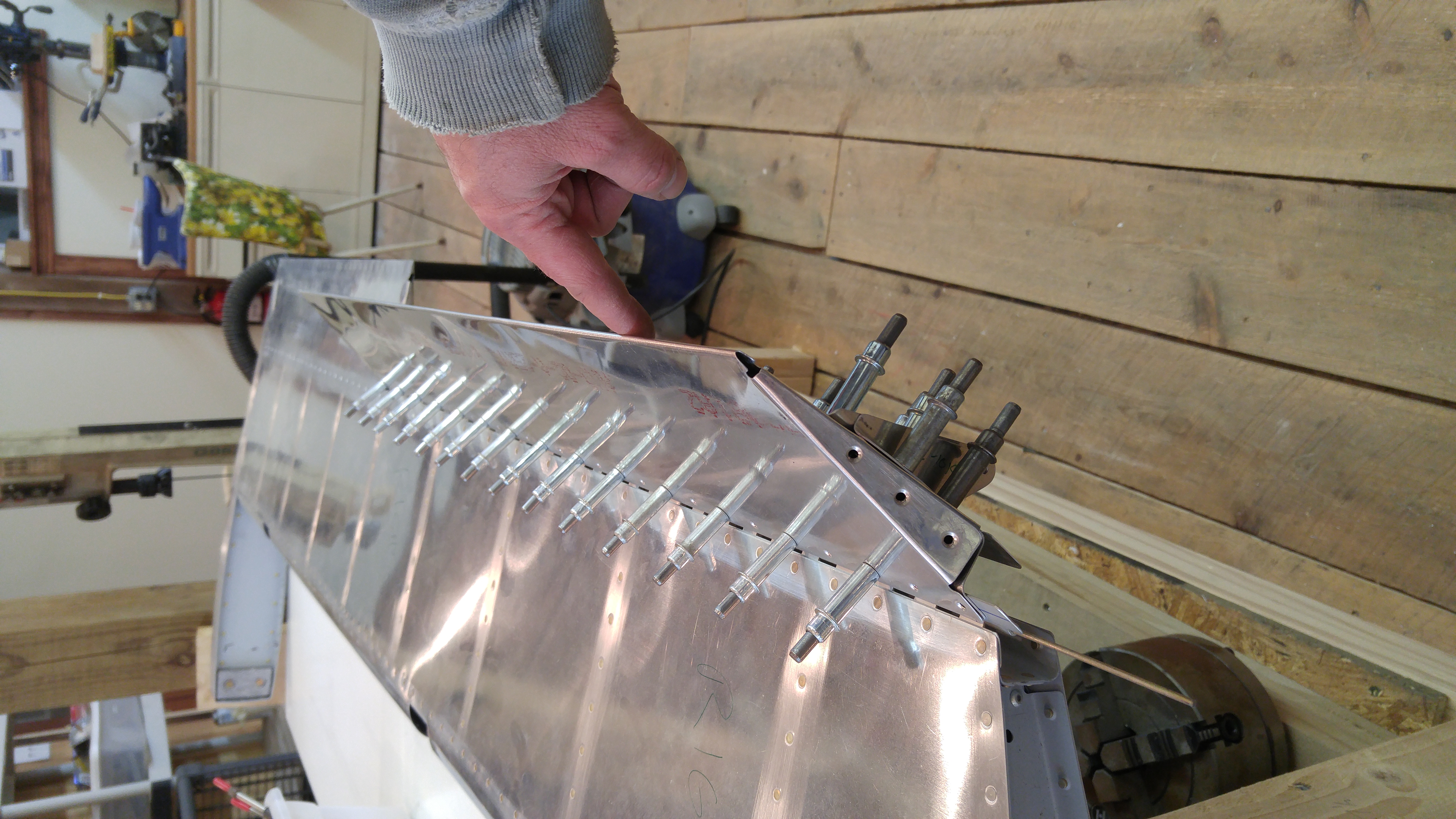
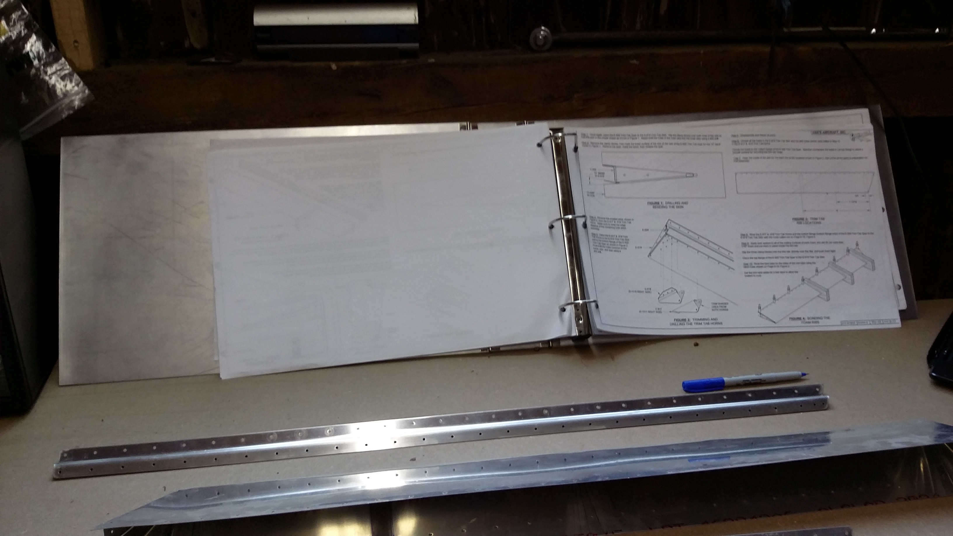
I spent 1.5 hours on the RH trim tab the other day and test fitted it on the elevator. Now I have to re-do the LH trim tab spar and then I can prime and final assemble both.
Total time so far 23.5 hours.
I spent 1.5 hours on the RH trim tab the other day and test fitted it on the elevator. Now I have to re-do the LH trim tab spar and then I can prime and final assemble both.
Total time so far 23.5 hours.
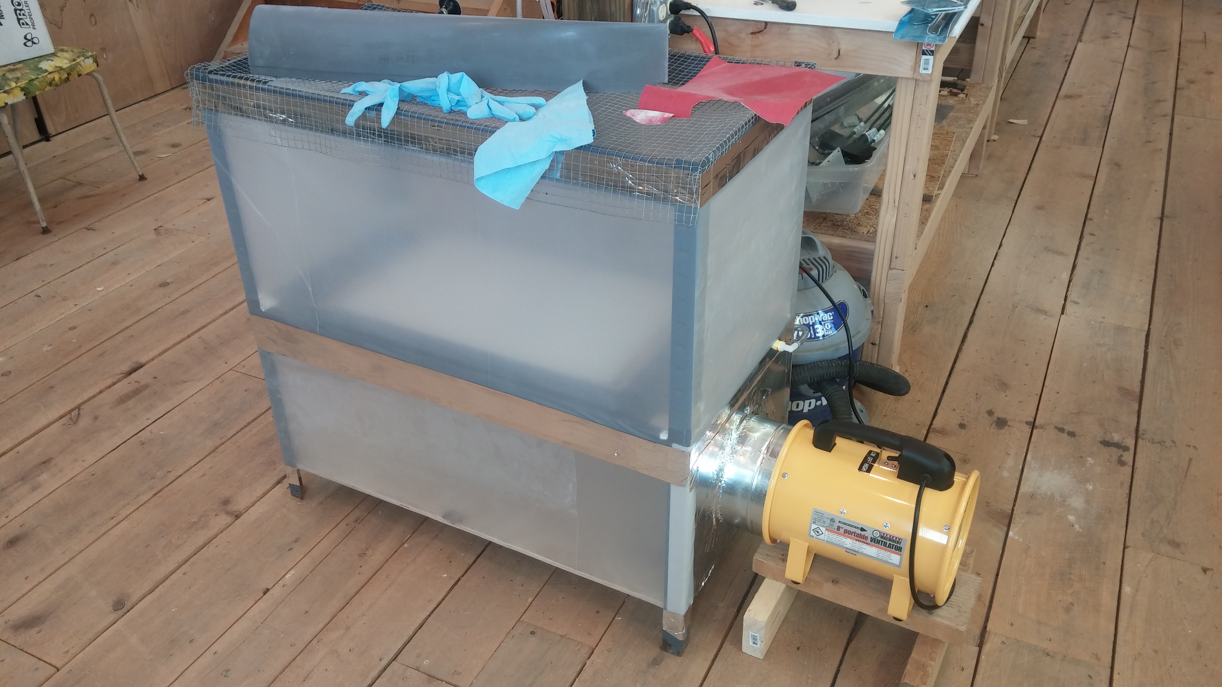
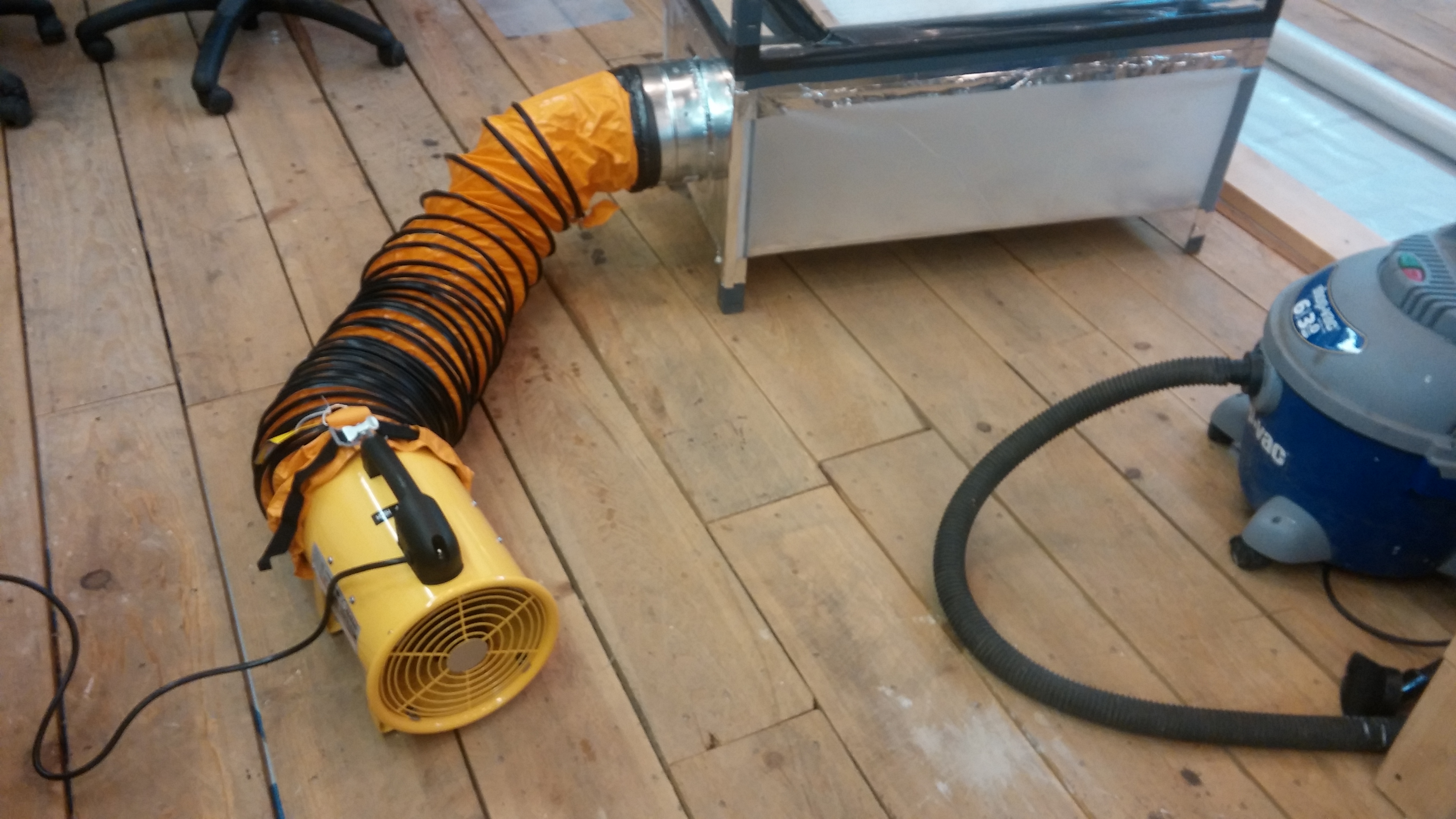
Today I modded the paint hood by placing the blower closer to the bottom plenum and got a much better air flow through it. The face velocity, while I wasn’t able to measure it directly, is quite substantial. I found that it works great for catching sanding dust when working on fiberglass fairings as well!
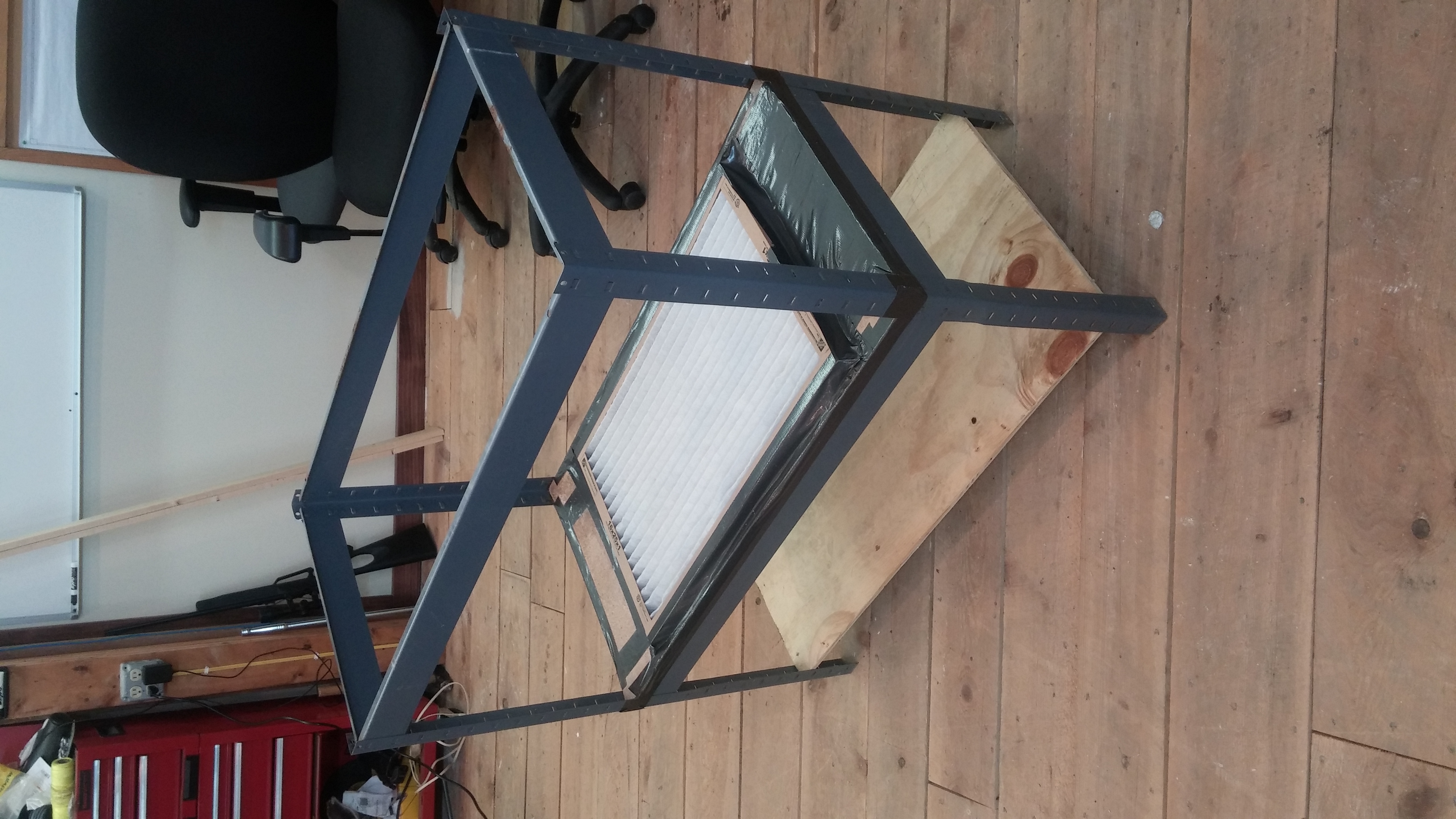
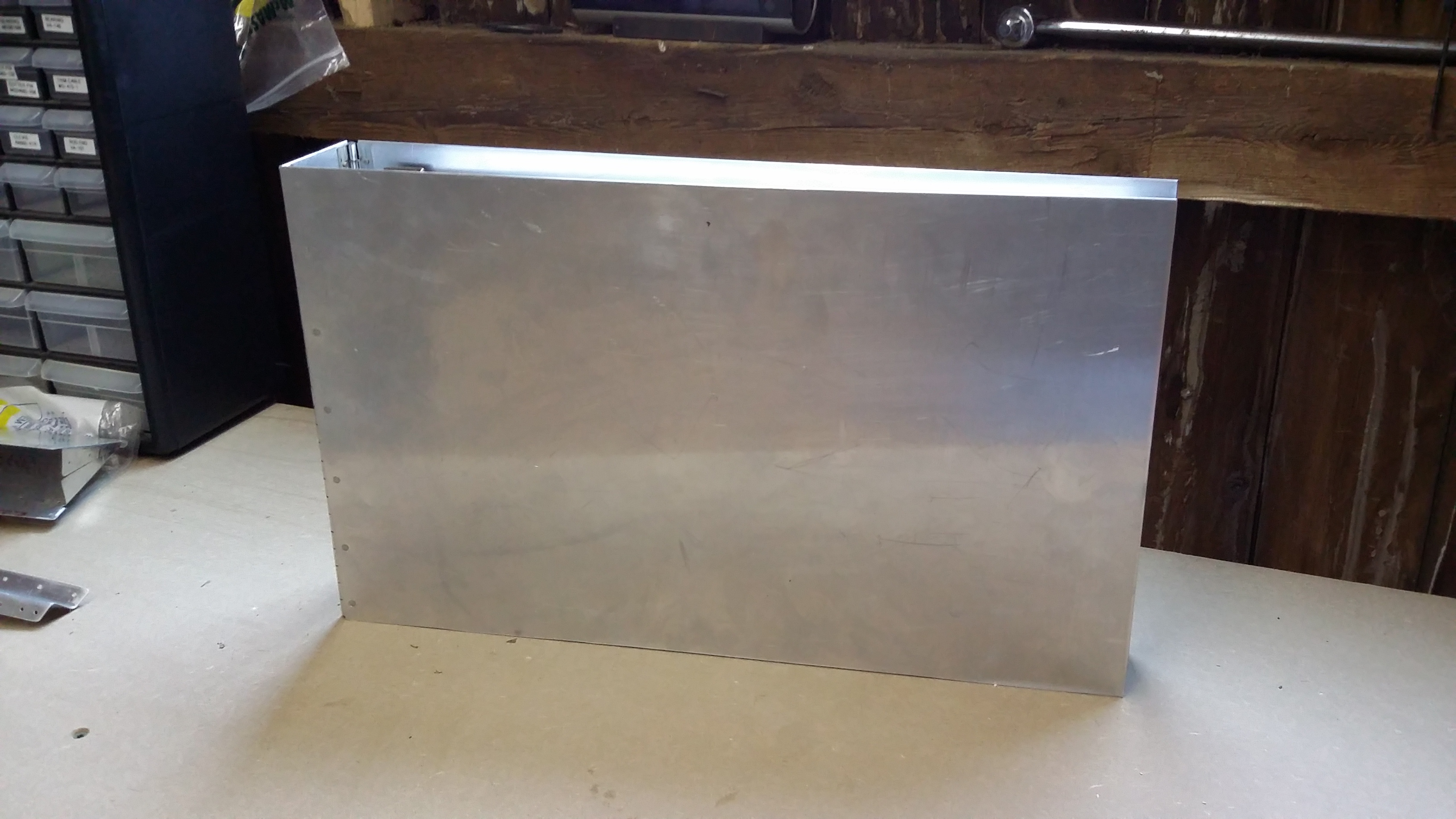
I had an idea for a painting “hood” to capture vapors and paint overspray for use when priming and coating small parts. I’ve seen similar things before, and thought I could make my own rather cost-effectively. At first, I was going to build a frame from scratch, but I realized I had an old metal shelf unit sitting around that I wasn’t using, because the shelves were rather weak particle board.
I figured this could be the basis of my painting hood. I did some brief research on fume hoods and found that best practice for paint booths is a minimum face velocity of 150 ft/min (chemical lab hoods are typically designed for 100 ft/min, go figure…) For this shelf, the open top of which measures 18″ x 36″, the minimum flow required to achieve this face velocity would be 675 ACFM.
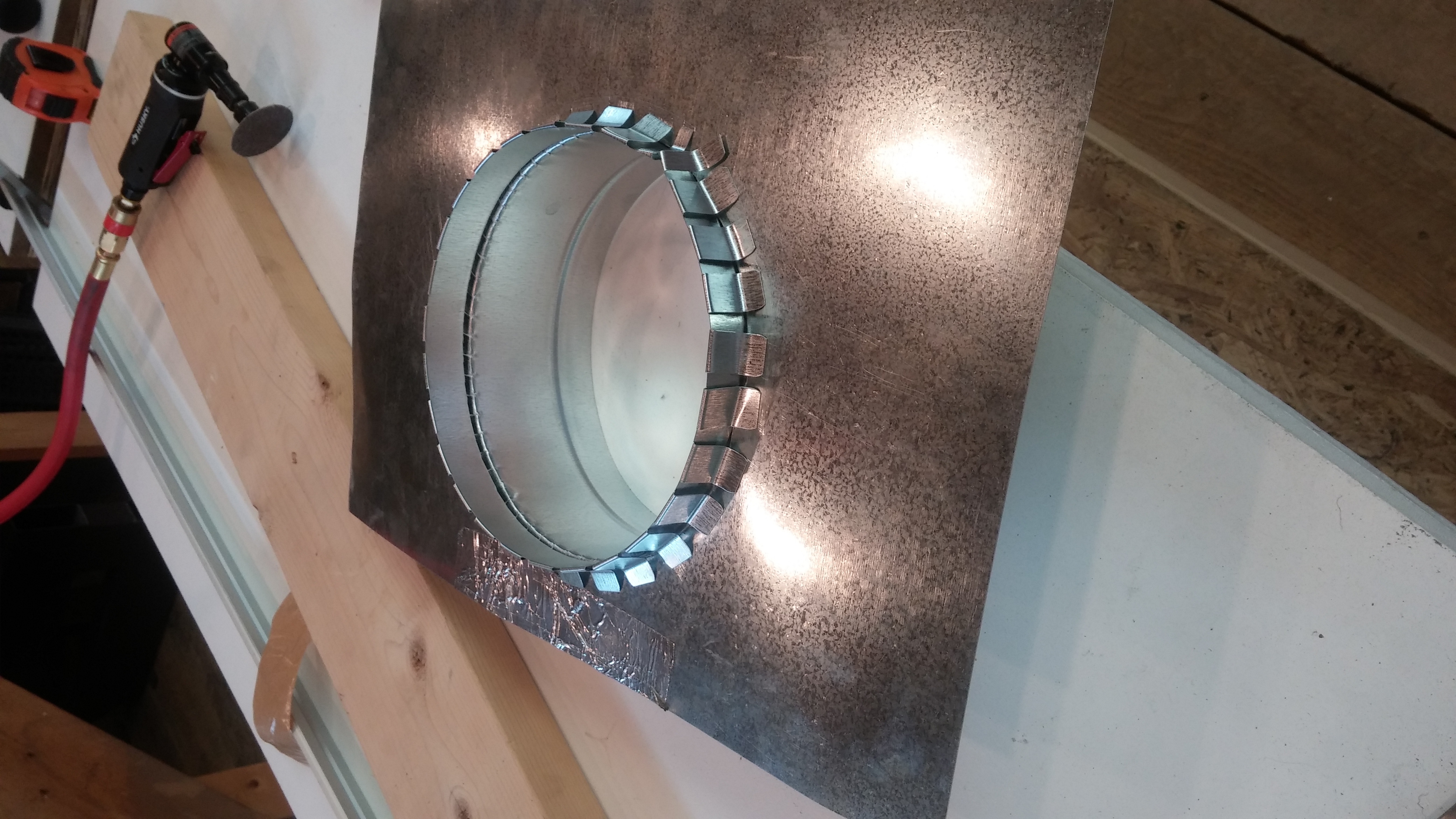
I hopped off to Harbor Freight and bought one of their 8″ ventilators (rated at 1590 CFM, pressure unspecified) and a flexible air duct. The 1590 ACFM should translate into a face velocity of 353 ft/min. Then, I headed over to Home Depot and bought some additional duct pieces and a cheap furnace filter.
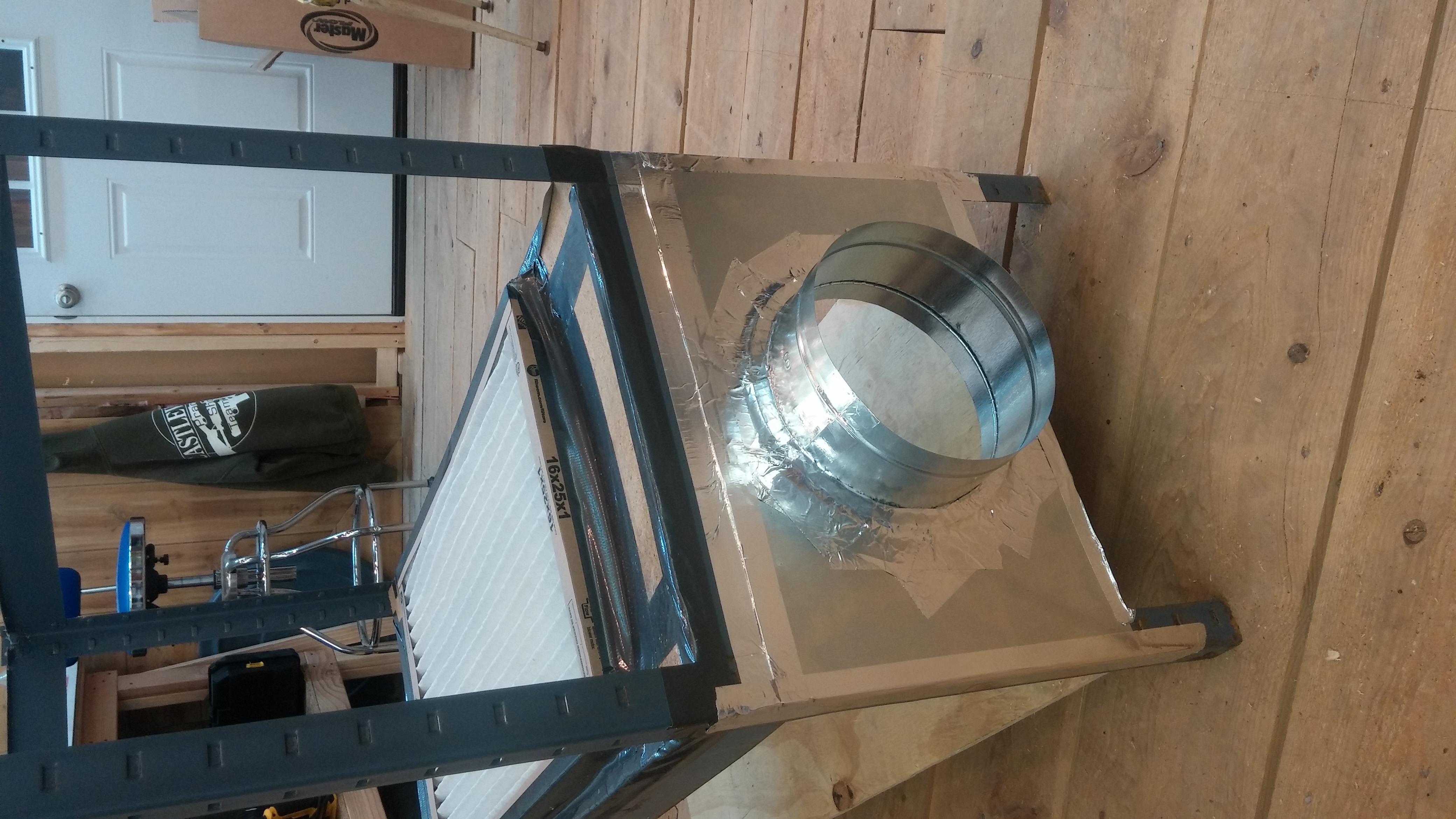
I cut the bottom shelf (which was warped from water damage) to have an opening for the air filter to fit over. Then I duct taped the edges of the hole to provide a better sealing surface. The furnace filter was easily secured to this with duct tape. The furnace filter will operate at an air speed of 572 ft/min.
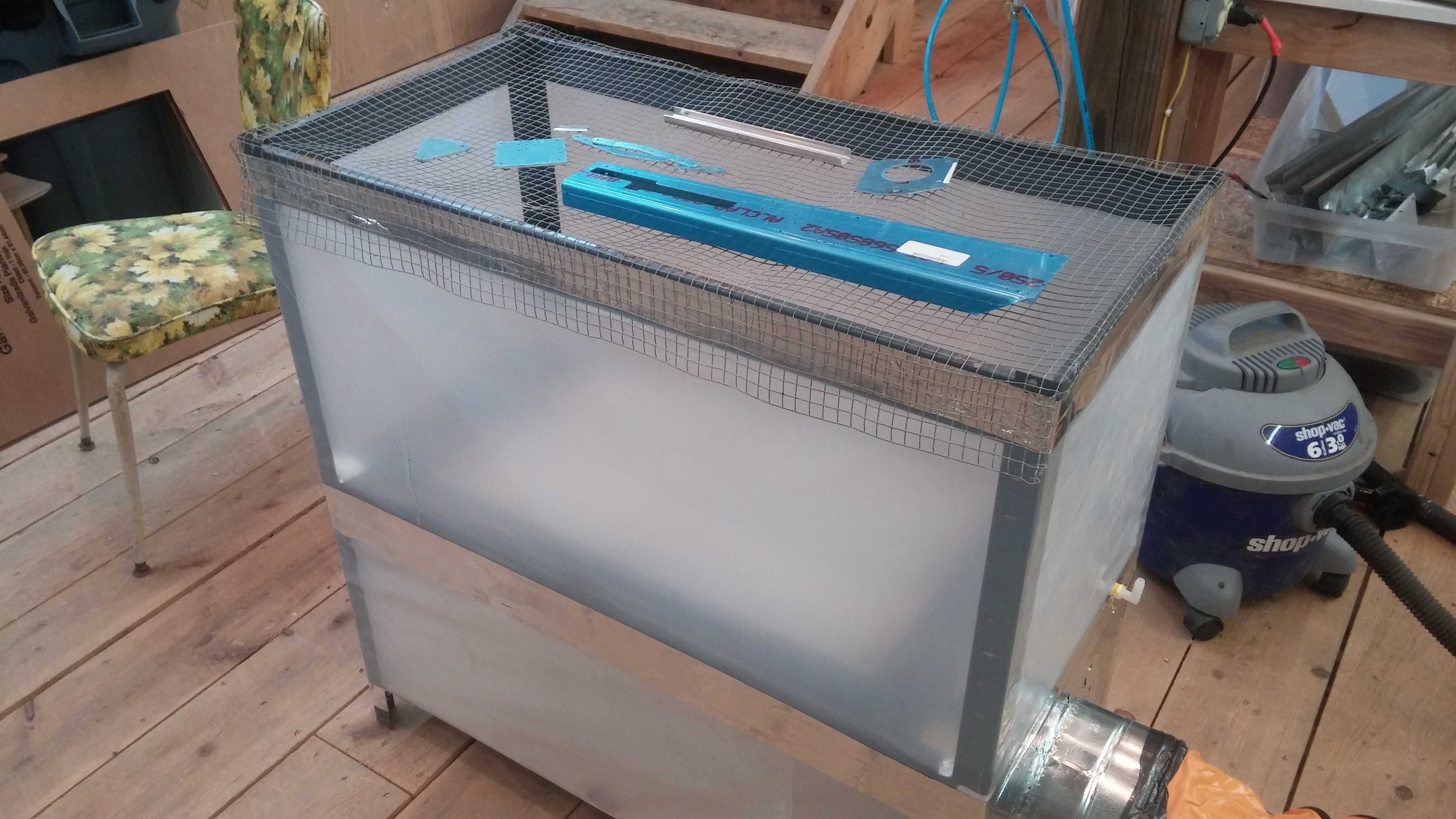
I had some duct tape and heavy (25 mil) plastic sheeting around. These, combined with the parts I had bought, and a small piece of scrap plywood, yielded this:
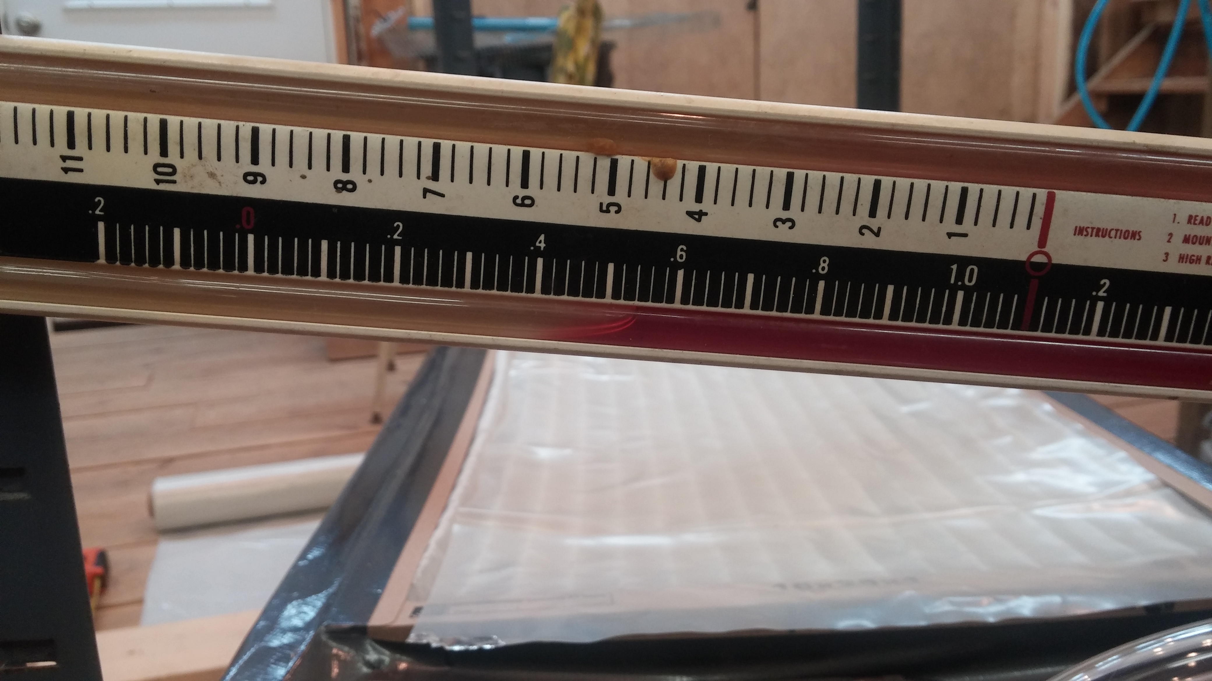
I then added a pressure tap and put my manometer to work. The differential pressure across a clean filter is almost negligible. I then covered the filter mostly with a piece of scrap plastic and the differential pressure across the occluded filter measures 0.52 inches of water column at the high speed setting on the ventilator. It will be interesting to see how much the filter changes from clean to dirty and how well it will work. I may have to use a more expensive filter rated for a smaller particle size for paint and primer.
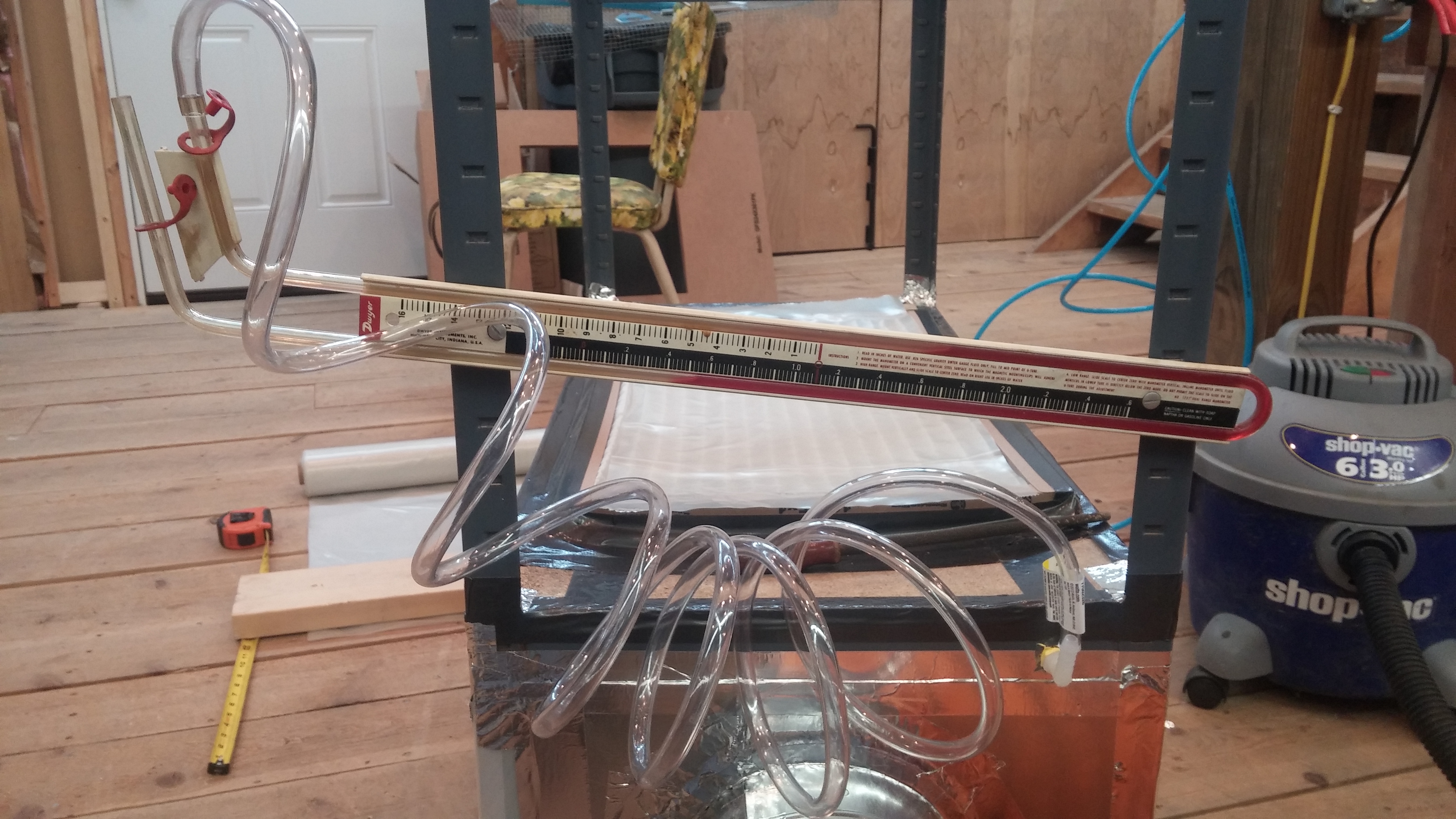
With the dP confirmed, I then finished assembling the unit with more plastic and metallic duct tape. The screen on top should allow for even painting of even small parts.
The ventilator will soon be hooked up to an exhaust duct to pipe fumes out of the workshop. Next step would be to borrow a pitot tube from work that we use to balance dust collector duct work and measure the actual air velocities in the hood and the duct.
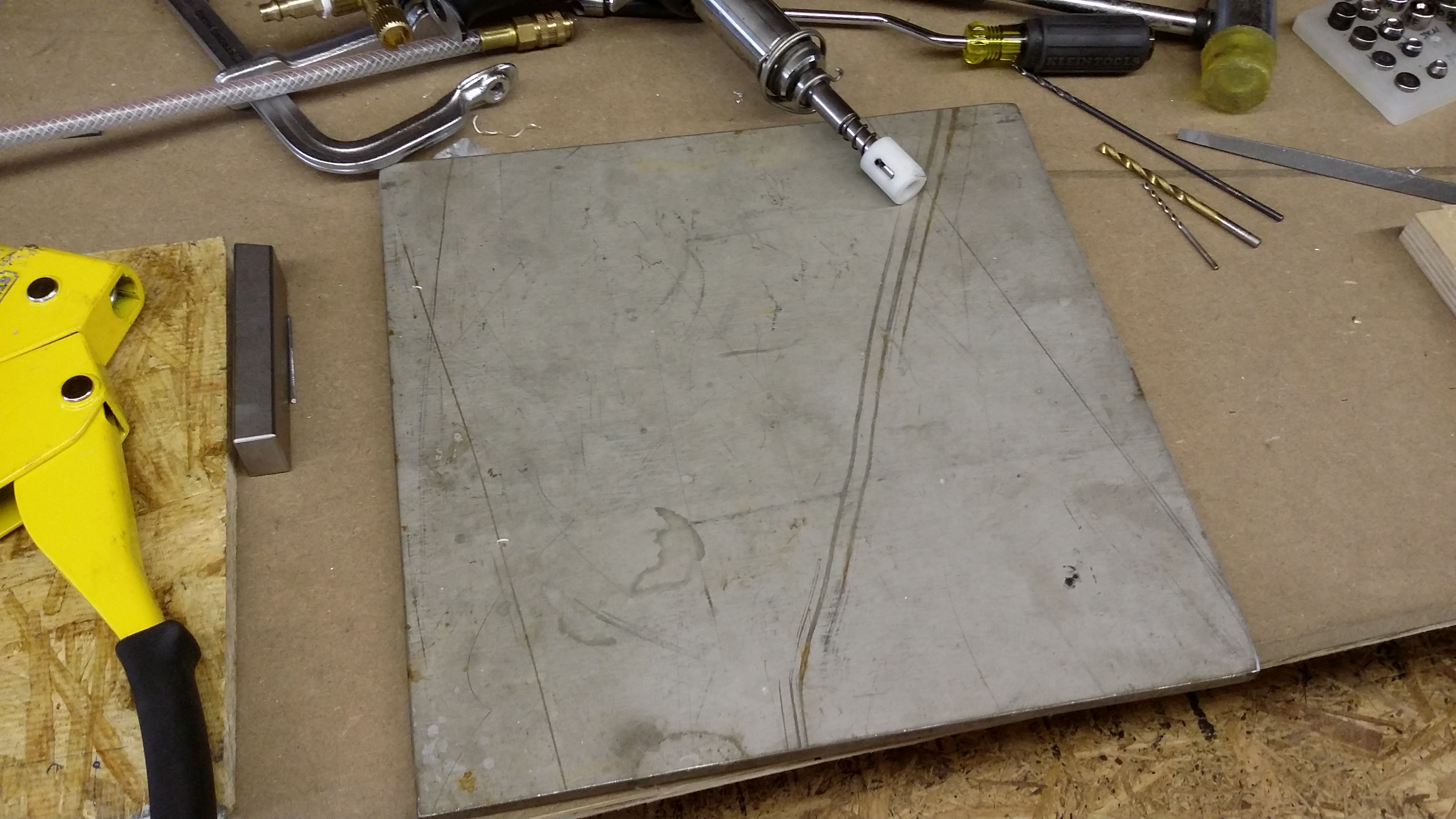
This evening I completed riveting the tailcone bottom skin F-1078 to the side skins F1073-L&R. I used the back riveting technique that others have used with success. My stainless back riveting plate allows 11 rivets to be done simultaneously. I may make a longer back rivet plate if it becomes an issue.
Also riveted F-1055-L&R to the side skins.
I had two rivets that needed to be drilled out and replaced. One required an “oops” rivet.
Time today 3:03. Total time 19:30.

First Rivet Driven! Left hand side of vertical stabilizer on front spar just above the middle inspar rib. Now we’re rolling!
Well, the workshop is now basically complete for the purposes of building an airplane.


All the utilities, including compressed air and electricity are complete.


Insulation and weather sealing are complete. Machine tools with the exception of the lathe and mill are set. Workbenches are placed and the sound system is functioning.
The only items left to do are:
Hang the ceiling
Build stands for and install the lathe and mill
Purchase metal brake/slip roll/ shear and install it
Finish wall sheeting around doors
Other than those items, which can be completed on the fly while building the airplane, it’s all set! On to finishing the vertical stabilizer.

Well, due to a lot of other obligations, I haven’t really begun building the -10 in earnest yet. But that is about to change!
Part of the “other obligations” has been to improve the workshop so I can work in relative comfort year round, in order to hopefully reduce the total build time. This has involved lots of amateur carpentry, drywalling, electrical installation, and in general plenty of relatively satisfying work. I only have a few items left before I can start finishing the tail kit and order the wing kit.
Some highlights:
New large doors (for getting big pieces in and out of the shop–this will be the main exit for the fuselage once it is done)


Ceiling mounted utilities including compressed air and electricity. Plus, LOTS of LIGHT. 21 can lights to provide warm incandescent list (3 switched zones to save power) and banks of fluorescent tubes mounted in the ceiling corners to provide bright flooding light.

A whiteboard for lists, calculations, sketches, etc.

Looking toward the main work area

In general, the shop is now (or will soon be) warm, draft free, and almost outfitted for work. I have to finish the ceiling insulation, build some shelves, and move the lathe and mill in (that may be able to wait a bit) and things will be good to go.
A time lapse video up to and including drilling and dimpling. I had an issue at the end with the microstop countersink slipping and I am waiting on some “oops rivets” to arrive to finish it. I’ll start on the right tab tonight.
[stream flv=x:/www.brunbergs.net/wp-content/uploads/2015/04/lefttrimtab1.240p.flv img=x:/www.brunbergs.net/wp-content/uploads/2015/04/TrimTabShot1-300×169.jpg mp4=x:/www.brunbergs.net/wp-content/uploads/2015/04/lefttrimtab1.mp4 embed=false share=false width=640 height=360 dock=true controlbar=over bandwidth=high autostart=false responsive=16:9 /]
I figured I could use some practice with basic sheet metal techniques. While I took the EAA RV Assembly SportAir Workshop back in January (Thanks to all the folks at EAA and KFDK who made that happen!) and completed the Van’s airfoil practice kit, I still have a ways to go until I feel my driven rivets are good enough to fly. So, I figured I’d do a little work.
At the same time, I was looking for a proper 11×17″ binder to protect my plans, but when I looked at the prices at Staples and other office supply shops (including Amazon) I figured I could do better for less (the cost of a simple binder at Staples is ridiculous–well over $40 for a thin binder, and better ones get up near $70-80 each!).
So I figured I’d combine the two needs into one. I ended up with a sturdy, handmade binder made of 3003 aluminum sheet (0.040″). I obtained the aluminum sheet from Metal Supermarkets, which conveniently has a retail location a short drive from my office. The piano hinges were sourced at Home Depot, and the D-ring was cannibalized from an inexpensive 8-1/2 x 11″ binder. Total cost, approximately $40, but I got some valuable practice at riveting, drilling, countersinking, dimpling, and deburring.
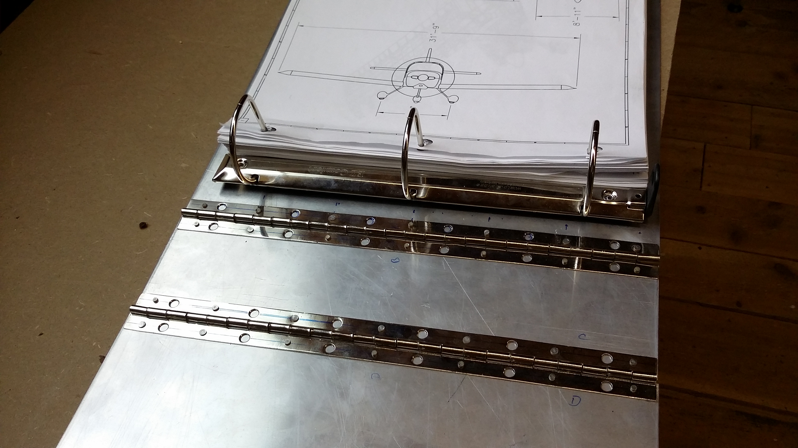
I didn’t use the pre-drilled holes in the Home Depot hinges because they were simply too large for the rivets I wanted to use and larger rivets would have been a waste here. You can see variability in the degree of the shop head development because I was experimenting with different settings on the rivet gun. I decided not to re-do them simply to remind myself of the significant differences.
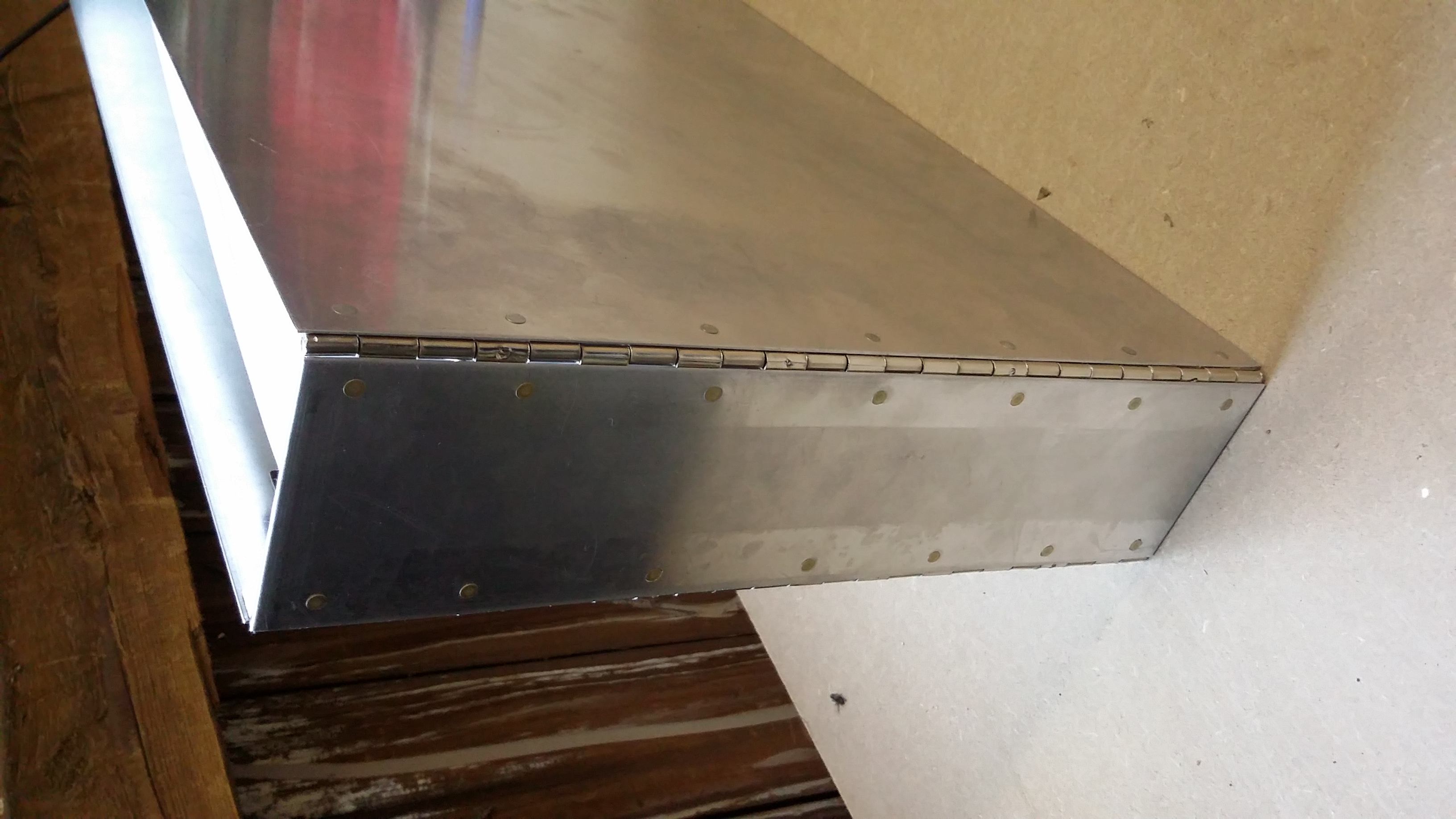
I back riveted the hinges to the spine and covers using a large stainless steel plate I happened to have lying around. I may polish the plate to get a better finish but this was acceptable for the purpose here.
A bonus to this binder is it is rigid enough to stand up and hold the plans properly without deforming the binder. I may add a clasp and a handle in the future, as well as possibly some holes for hanging hooks if I find that may be useful.
Finished the first work table last night.
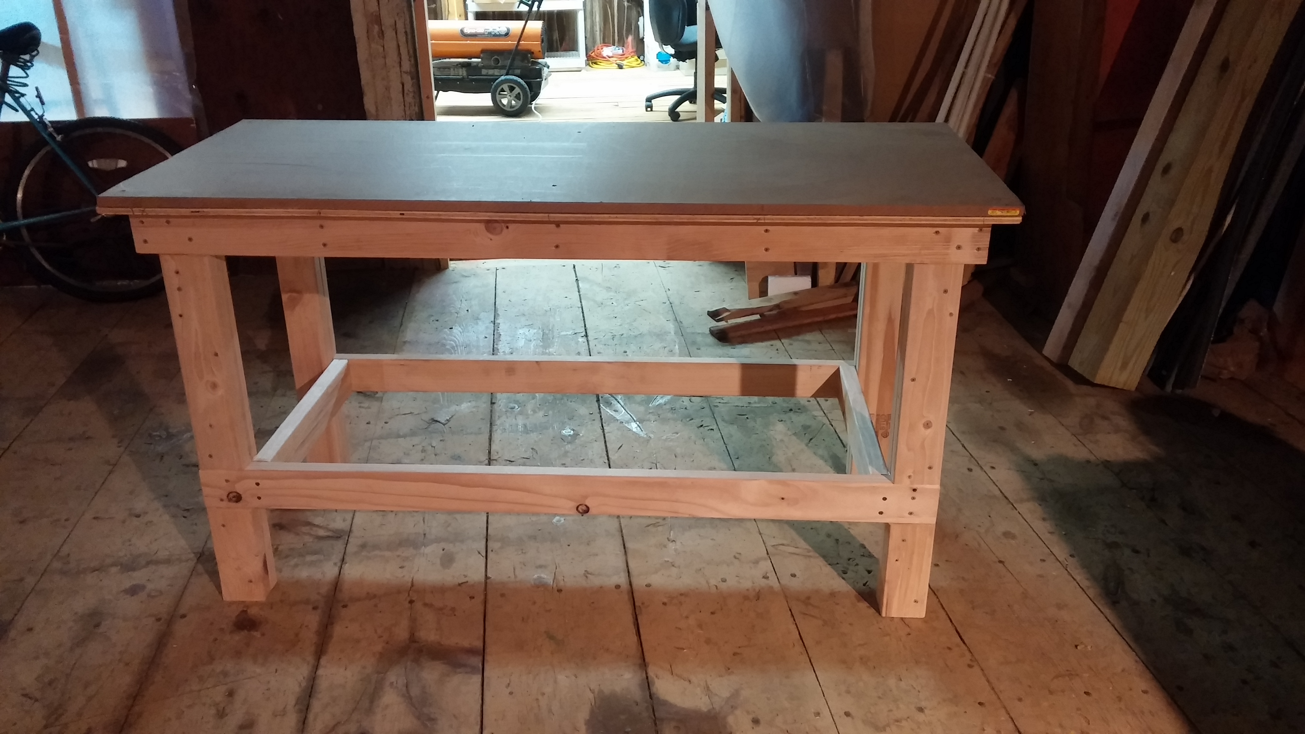 I added a 1.5″ lip all the way around for clamping, and built the top using 1/2″ plywood with a 3/4″ MDF tabletop. The plywood is glued on to make the table rigid, while the MDF is affixed with recessed screws.